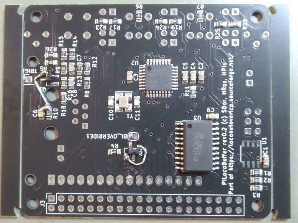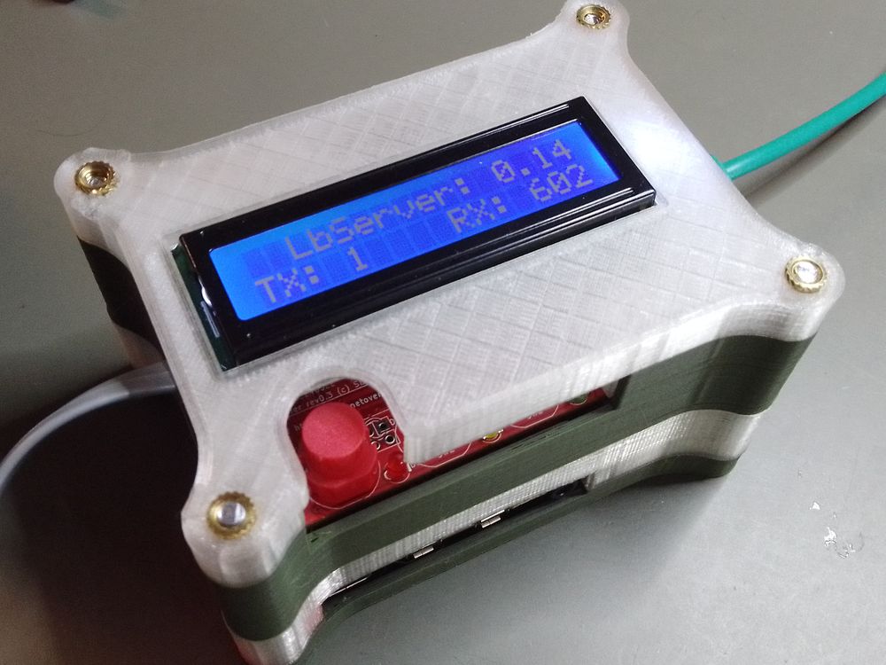
The board sits on top of a Raspberry Pi with a 40 pin GPIO header. It contains an AVR micro controller that interfaces directly to LocoNet and connects directly via UART lines with the RasPi.
Releases of the manufacturing data, firmware, etc will be done in the SourceForge file release system. There are also various files to put PiLocoBuffer into a case.
This pages is about various themes. If you want instructions on building the hardware and installing the software please follow:
More Information on special themes:
Designer of schematic and PCB is Heiko Rosemann. The KiCAD files can be found in the subversion repository. For a PDF of the schematic klick here.

The board connects to the Raspberry Pi via the 40 pin GPIO connector. All RasPis beginning with version 1 B+ have this kind of connector and the board is expected to work with all of them. The board contains the following major building blocks:
A two line LCD connects directly to the GPIO header over a buffer. A new version of LbServer displays status information on this.
Central component is an AVR microcontroller. It interfaces directly to the LocoNet. The board contains the usual six pin western socket. Three status LEDs are intended to inform about received/transmitted messages or error situations.
There are three connections between the AVR and the RasPi:
Two wires for LocoNet messages between LbServer running on the RasPi and the firmware running on the AVR. This connects a hardware UART of the RasPi with the hardware UART of the AVR.
In order to load the Flash and EEPROM of the AVR from the RasPi the SPI pins of the RasPI plus one IO line are connected to the SPI pins plus reset of the AVR.
Raspberry Pi has a special feature to identify a board and to load respective driver to use the hardware. Normally this shall be implemented with a dedicated EEPROM. We try to emulate this from the firmware inside the AVR and use the EEPROM inside the AVR to store the information that is read out by the Raspberry Pi at boot time.
Three LEDs are connected to the AVR. The firmware switchs them on at boot and off either when the RasPi accessed the ID EEPROM early in its boot process or after a timeout of 10s.
Note: reboot of RasPi does not reboot the AVR, likewise reboot of AVR - e.g. when flashing a firmware - does not restart the RasPi and therefore does not trigger ID EEPROM access.
| Label | color | AVR port | Usage by firmware running on AVR |
|---|---|---|---|
| D1 | red | PORTC 0 |
not yet in use, maybe detection of valid signal level |
| D2 | yellow | PORTC 1 |
shortly on for each message sent to LocoNet |
| D3 | green | PORTC 2 |
shortly on for each message received from LocoNet |
A button “SW1” is used to trigger shutdown and boot. It is recommended to use this, because it is known that the SD card can be damaged from powering off in full operation - especially if used in writable mode, which is default.
In order to use kernel drivers for the power button and LCD, we need to load the
respective drivers. This can either be done by editing the config.txt file on the
SD card or by putting this information into an ID EEPROM on the board.
The firmware running inside the AVR emulates this I2C EEPROM.
See build instructions of firmware for
technical explaination.
The firmware running on the AVR ‘ATmega328PB’ is implemented by Stefan Bormann.
It is based on the Embedded Loconet
project. The source code
can be found in the embeddedloconet subversion repository.
The firmware interfaces directly to the LocoNet. The processor internal comparator is used to implement correct levels according to the LocoNet specification. Even hysteresis could be implemented thanks to the fact that the output of the comparator is connected to a pin. The processor internal UART is used to receive bytes from LocoNet.
How to build it yourself is on another page.
In theory the board behaves like any other LocoBuffer style device talking over UART with 57600 Baud 8N1. It can be used by all sorts of different software.
But the board was built with LbServer in mind. Therefore a new version of LbServer is developed by Martin Pischky and Stefan Bormann.
The on board LC display is used to display the status of the program. Lower line contains the number of received and transmitted messages to/from the board. The upper line will show the IP address of the RasPi or any normal or error condition that is of interest. LbServer talks to the display over an existing kernel driver.
Additionally LbServer will learn to log information directly to the system journal. We will supply a configuration file to start LbServer from systemd at boot time.
There is a Forum thread where we discuss new developments and report progress. Please do not try to order boards here, there will be a dedicated thread if we ever do “Sammelbestellung”. Additionally you see pictures of the various stages of development below.
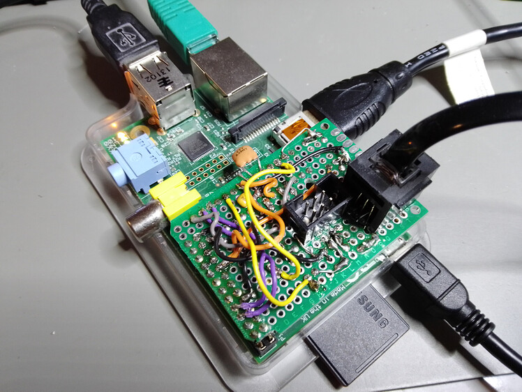
Back than I only had a RasPi version 1 B from stone age, still with 28 pin GPIO header.
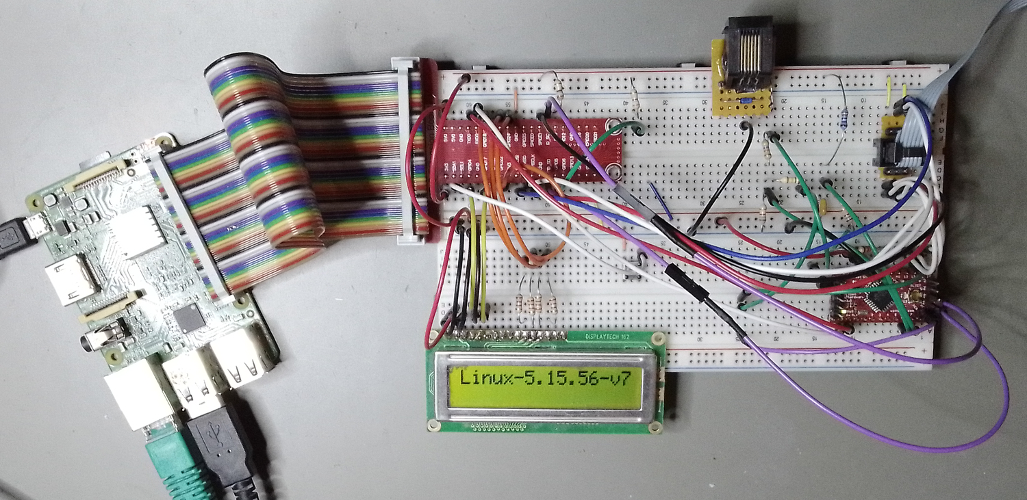
Firmware and LbServer development is done on RasPi version 2 with this wildly wired breadboard.
These are renderings made with the CAD program. This is a version before the first manufactured prototype.
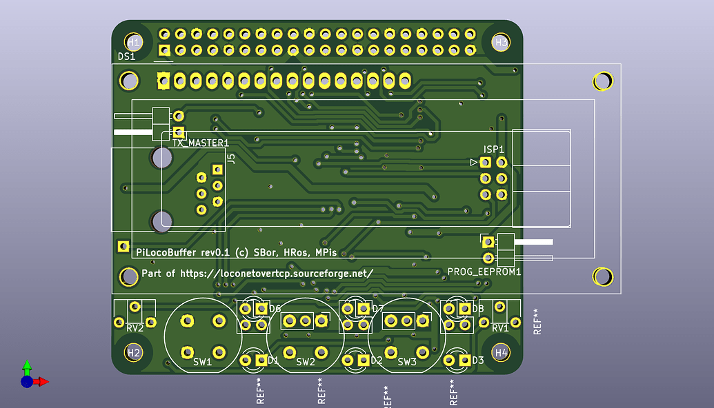
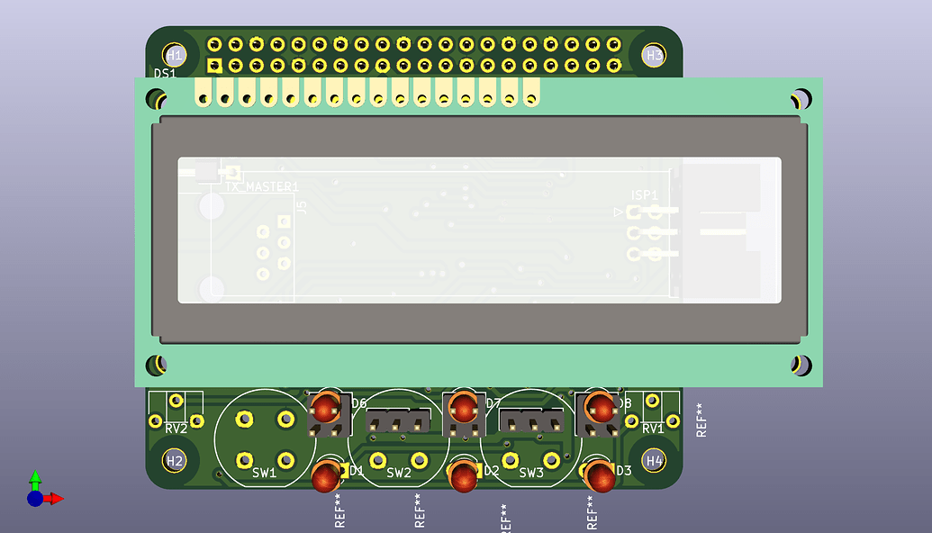
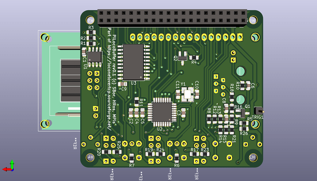
Winter 22/23 Heiko ordered a batch of 10 prototype boards.
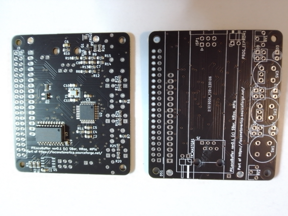
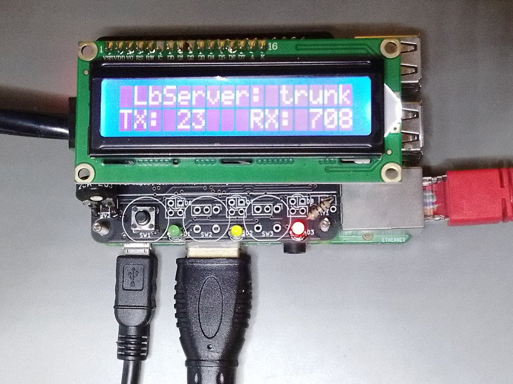
Found one bug in the first prototype board:
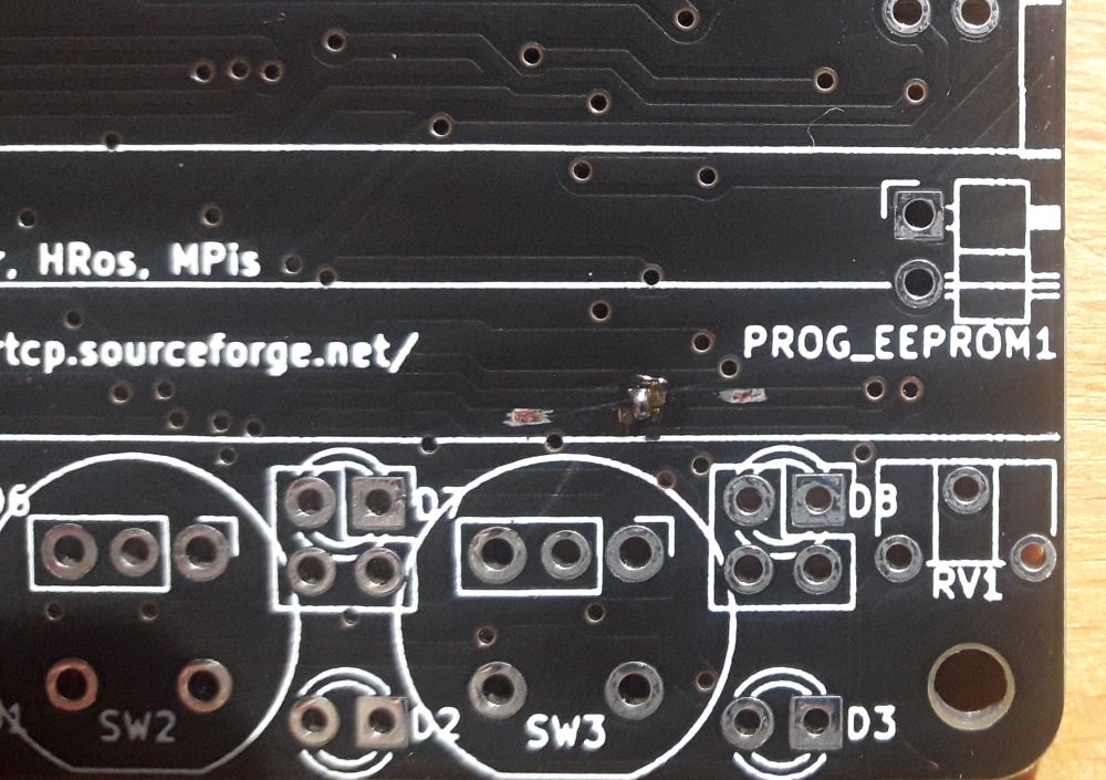
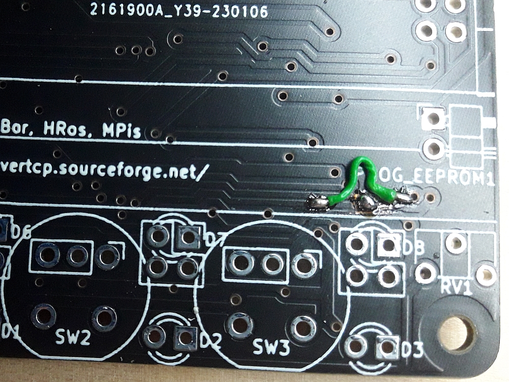
On the version 0.1 of the pcb the lines SDA and SCL are swapped. To fix cut traces and add two wires:
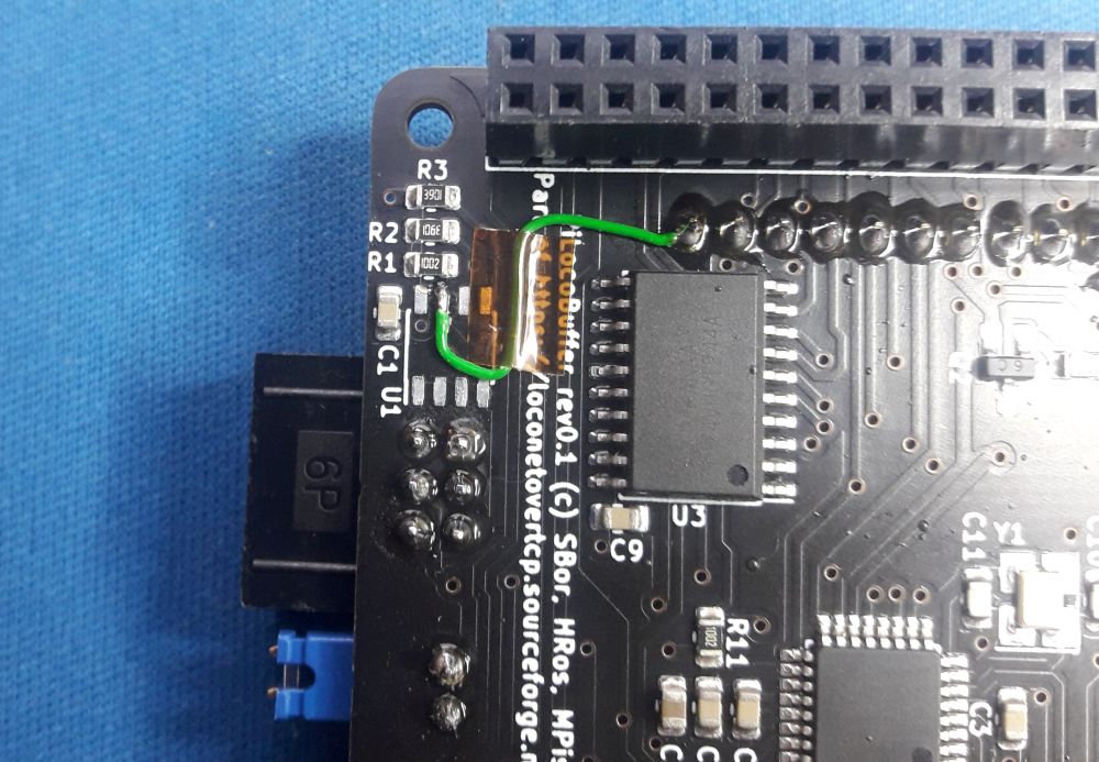
There are some problems with the backlight in the drivers (Backlight is off for “Power off” message). We fixed this by switching the backlight permanent by jumper:
Versions 0.1 and 0.2 had a hardware bug with swapped pins for emitter and collector for both transistors. One fix is to solder new transistors on the C/E pads reversed with a wire for the base.
